Loading and viewing UCFs with ShapeViewer
Before you start
Starting the program and loading files
- First, start up ShapeViewer from the .jar file. You can either double-click on the file, or run the file using the Terminal (on a Mac) or the command prompt (on Windows).
myprompt% java -jar -Xmx500M ShapeViewer.jar
- Load your UCF by selecting "Load Shape..." from the File menu. You can load ucfs, objs, off, tm, and dx files.
- You can load multiple files by using Ctrl- or Cmd- click in the "Load Shape..." window. For example, we could choose a left and right thalamus ucf file, which after loading would look like this:

- You could also add shapes later to view multiple files at the same time with "File → Add Shape..."
Orienting your image in space
- To reorient your shape in space, either click and drag in the window, or for predefined orientations, choose "View → Scene Orientation → Standard Orientations → +/-X, +/-Y, +/-Z". Click the image below to enlarge it.

- You can also add "Favorite" Orientations in the Favorites menu under "Scene Orientation", so that you can use a predefined custom orientation for a set of ucfs from different subjects.
Changing the appearance of your UCFs
- You can change the color, draw mode, lighting, and background color of your UCFs.
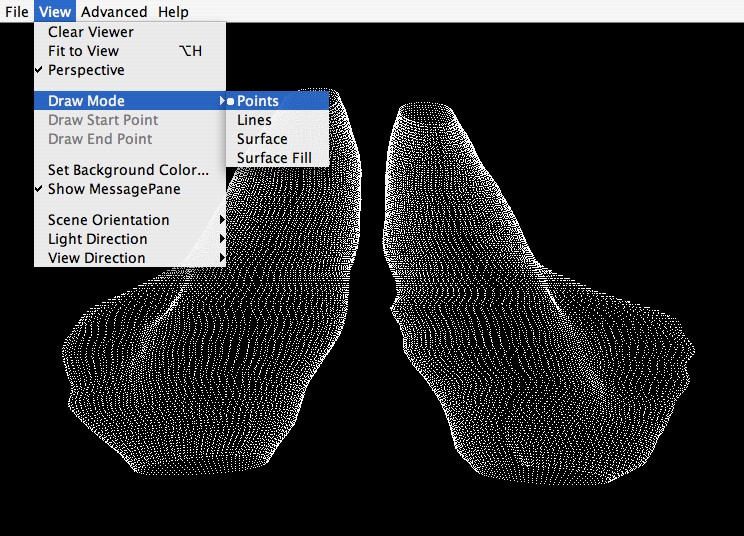
- Changing the "draw mode" will change whether your UCF is displayed as a series of contours (lines), a series of points, a tesselated surface, or a filled surface. Select the "draw mode" from the "View" Menu. "Surface fill" may require more memory for whole cortex UCFs, and involves changing the lighting on the object*. Examples of each mode are shown below:


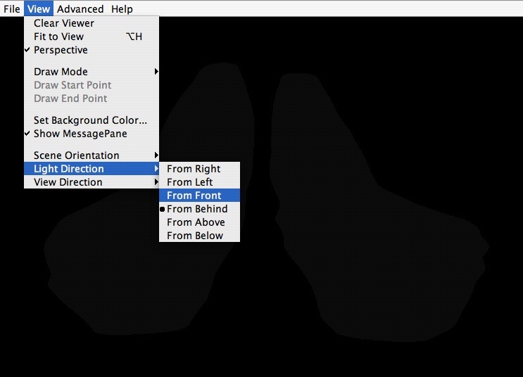
- *If you choose "Surface Fill" as your draw mode, at first it may seem that your ShapeViewer screen has gone black (you may see a faint grayish-black outline of your UCF). This is because your lighting settings are not set properly. You must set the "Light Direction" under "View" to "From Front", and the view direction to "From Front".

- Changing the color can be done for each UCF individually using the "Color" button on the right panel. If your UCF contains 4D data about variance or surface deformation (such as UCFs that are outputted from the statistical program R), then you can create a color map to show the values embedded in the mesh. In the "Color Map Editor", either click on a color (if you have 3D data), or click in the Red/Green/Blue columns to change the amount of each color.
Double clicking in the green column allows you to color your ucfs green, as shown in the screenshot to the right. UCFs are colored individually, and can be selected either by clicking on the UCF in the 3D view, or selecting the Shape number in the "Color Map Editor".


- In the color map above, if you had p-maps (4D data) like we have here, you could choose to color your object to reflect p-values contained in the fourth column of the UCF, which we will explain next.
Color Bars
- Color bars are stored as .xml files that can be edited later in your favorite text editor. For example, if, while clicking and dragging the color sliders, you are getting numbers like 0.3434512423, you can edit these later to be shorter--0.3 even, for example.
- If you have a color bar already available, you can load it by clicking the "Color" button again (which pops up the "Color Map Editor"), and then click "Actions → Load..." Select your .xml or .colormap file and click "Apply", then "Ok" when you're done.

- If you do not have a color map readily available, you will have to make your own. Use the red, blue, and green sliders to create a color map by double clicking in the columns. You can also change the Min and Max values to match the attributes of your UCF, which are displayed to the right of the color bar.

- Notice the little square where you clicked. You can double click on the red, green, or blue line again to create more little squares and change your color values depending on the attributes of your UCF. Here is an example with a spectral colorbar which has then been applied to our UCF.


- Now, depending on your taste, you may like this or think it is very ugly. In this case, the rainbow color bar isn't all that meaningful, since it doesn't show us significant surface deformation, just gives an overall view of what the p values are. Here all our p values are positive, with the most significant being in red, and the least significant in purple. We could, instead, load a color bar that colors only areas on the UCF where the pvalue is between 0 and 0.1. You can also choose to download our pvalue color bar (right-click to save). This would look like the figure below:


- Notice that in the figures above, the shapes in red in the rainbow thalamus and the shapes in pink in the p map look very similar. You can tweak the color bar to suit your data and bring out results that you think are important.
Saving Scenes and Images
- Under the File menu in ShapeViewer, you will notice that you can either save "scenes" or "images". Saving a scene allows you to reload the UCF, colored and oriented as you saved it, in ShapeViewer for a future session.
- Saving an image allows you to save out a static .jpg that cannot be reoriented or edited later in ShapeViewer, but that can be loaded in Photoshop or used as a figure in a paper.
For more information on ShapeViewer, read the documentation manual that comes with the ShapeViewer download on the LONI website.


